Keyboard Synthesizer with Drums and GUI
3C10 Group 7

This DIY digital synthesizer and drum set project is perfect for any music enthusiast, hacker, or programmers who are interested in digital signal processing (DSP), modern music production, electronics and programming. Use an Arduino and Rasperry PI Pico (optional) to create your own DJ deck, complete with a synthesizer, effects (attack, delay, sustain, release) , keyboard and drums. Develop some applied practical skills and add your own twists following along with this project!
"The most exciting phrase to hear in science, the one that heralds new discoveries, is not 'Eureka!' but 'That's funny...'" - Isaac Asimov
Below is a table of the main parts you will need to create the basic elements of this project. Don't fret! If you do not have exactly resistors or capacitors, you can experiment with designing your own filters, etc.
| Component | Quantity | Specifications | Purpose |
|---|---|---|---|
| Core Electronics | |||
| Arduino Nano 33 IOT | 1 | Or compatible microcontroller (Uno, etc.) | Main processor for the synthesizer |
| Raspberry PI Pico | 1 | Or compatible microcontroller | Main processor for drums and GUI |
| Breadboard | 1 | Full-size recommended, multiple may be helpful | For prototyping the circuit |
| Jumper Wires | 20+ | Various lengths, female connectors may be helpful | Connecting components |
| Keyboard/Input Components | |||
| Keypad | 1 | Alternatively use 8+ push buttons | Keyboard keys |
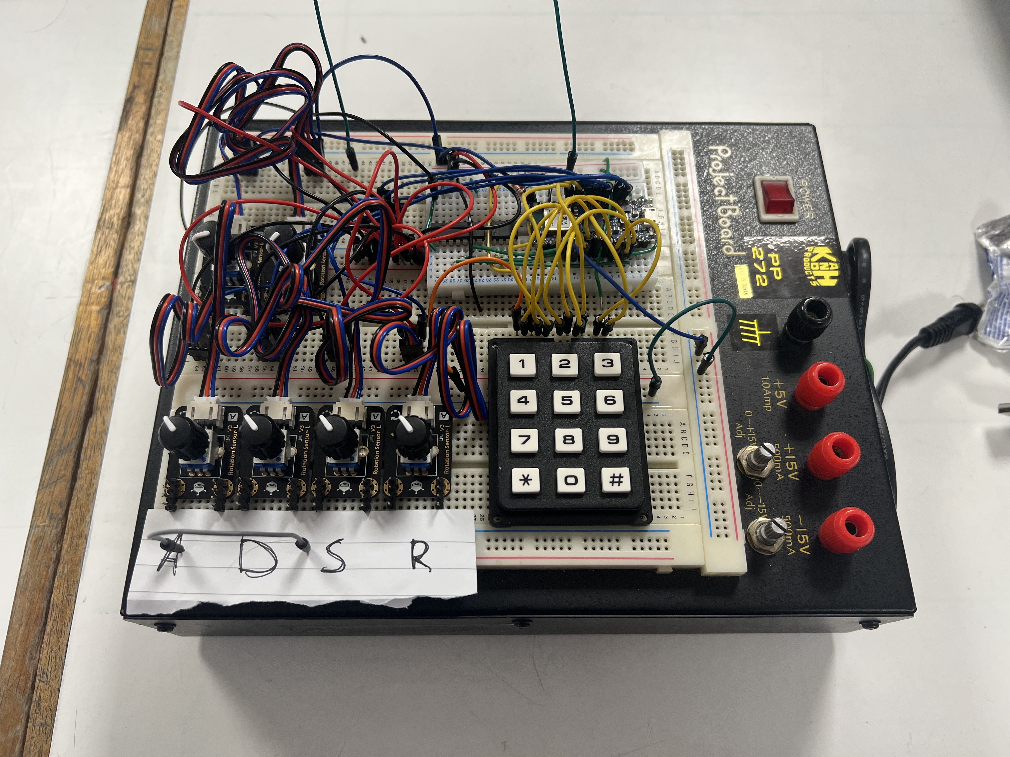
| Potentiometers | 6 | 10kΩ linear | Parameter controls for keyboard (attack, sustain, release, etc.) |
| Pull-down Resistors | 8+ | 10kΩ | For button debouncing (only necessary if you use push-buttons rathe than keypad) |
| Synthesizer Components | |||
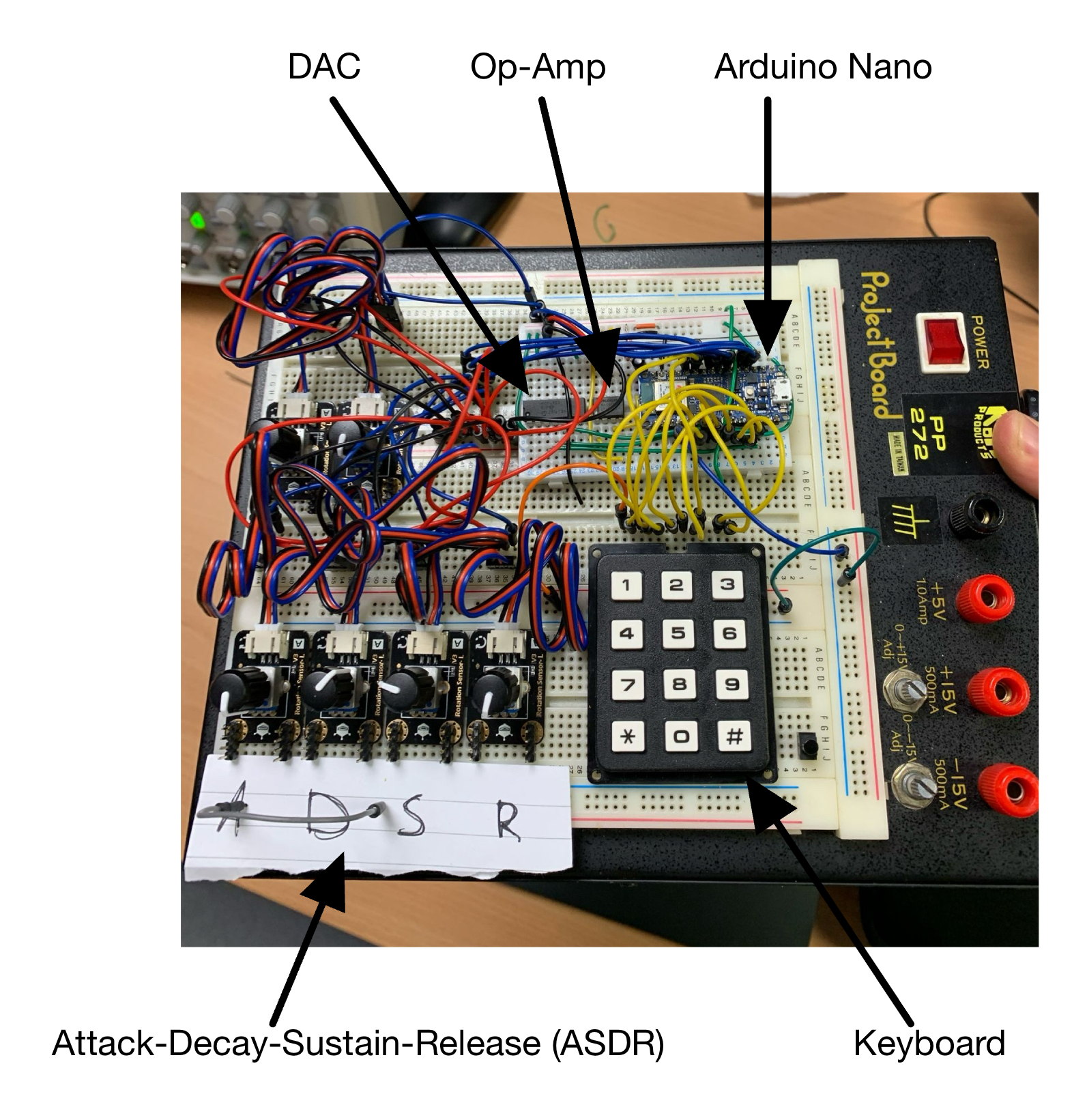
| Digital to Analogue Converter (DAC) | 1 | MCP499 (12 bit DAC) or similar | Signal generation |
| Op-Amp | 1 | MAX417 or similar | DAC signal conditioning |
| Resistors | 2 | 10kΩ | For RC filter |
| Capacitor | 1 | 1μF | For RC filter |
| Output Components | |||
| Speaker | 1 | 8Ω | Audio output |
| Audio Power Amplifier | 1 | LM386N or similar | Amplify audio signal | Resistors | 1 | 10kΩ | For power amp. | Potentiometer | 1 | 500kΩ | For Volume control |
| Capacitors | 2 | 0.33μF, 220μF | For power amp. |
| GUI Components | |||
| OLED SPI Display | 1 | Any display that uses Adafruit SSD1306 drivers e.g. MDOB128064BV-WS | Display synthesizer parameters |
| Joystick | 1 | With push button e.g. VMA315 | Menu navigation |
| Drum Machine Components | |||
| Touch sensor | 4 | Capacitive touch sensor such as DFRobot v2 | Drum trigger pads |
The main goal of this project was to utilize an analogue component with an embedded component to create a system that functionally produces and processes audio signals for musical applications. Our system integrates the envelope components of the synthesizer with the touch pads of the drum set to create a model of a DJ set that allows for real-time sound creation and manipulation. This project demonstrates the use of practical applications in circuit design as well as developing and processing audio signals for output, combining analog signal conditioning with digital control systems.
Originally we set out to make a vocoder for this project, but after much testing and consideration we decided to pivot. Some of the elements we built however, remained useful. The first thing we built was an audio power amplifier, so that we could experiment with playing different sounds through it, and how different filters would affect the audio. You can try connecting the green wire to different types of input and playing with the volume controls.
Our goal in this lesson is to turn eight push‑buttons (or a tiny telephone‑style keypad) into a two‑voice digital synthesizer that feels surprisingly “analogue” thanks to a full ADSR envelope and rich lookup‑table waveform. Everything runs on the Arduino Nano 33 IoT driving an MCP4922 12‑bit DAC, filtered, then boosted by a modest op‑amp/LM386 stage. When you finish this page you’ll be able to play chords, tweak attack & release in real time, and hear clean, artefact‑free notes through a speaker.

The eight note buttons map to a one‑octave A‑major scale: A4 → A5 (A, B, C♯, D, E, F♯, G♯, A). Because we store the scale as offsets from A4, the synth can easily transpose. Use the Oct ▲ and Oct ▼ buttons (pins A7 & A6) to shift the entire keyboard ±4 octaves.
The Nano’s SPI bus clocks data into the MCP4922 at 8 MHz. We use only channel A (12‑bit resolution). A simple RC low‑pass pulls the stair‑stepped output down to audio‑bandwidth, and a unity‑gain MAX417 buffers the line before it reaches the LM386 power amp. Frequency pots (A0 & A1) feed 10‑bit ADC readings directly into the firmware’s tuning maths, while four more pots land on A2–A5 for the envelope knobs. Eight buttons on D2‑D9 trigger the note logic; two extra buttons on A6/A7 bump the octave.
| Poly‑Synth‑only parts | Qty | Notes |
|---|---|---|
| MCP4922 12‑bit DAC | 1 | datasheet, channel A used |
| MAX417 (or any rail‑to‑rail op‑amp) | 1 | Unity buffer / RC low‑pass |
| 10 kΩ potentiometers | 6 | Attack, Decay, Sustain, Release, Fine‑tune, Semitone |
| 12‑key silicone keypad (or 8 push‑buttons) | 1 | Note triggers |
| RC filter | 1 × 10 kΩ + 1 µF | 1st‑order low‑pass ≈ 16 Hz fc |
| LM386, speaker, vol pot | 1 set | Reuse from Lesson 1 amp |
rich_lookup_table[256] – a pre‑cooked additive‑synthesis
waveform. 256 samples keeps the phase counter byte‑sized and speeds
table fetches.struct Voice – holds everything per note:
updateEnvelope() – runs every sample. Key idea: during
DECAY we subtract env_decay until envLevel
hits decayTarget, then snap to
sustainLevel. RELEASE is a straight linear fall under
env_release.generateAudio()
updateEnvelope().phase += phaseInc; if over 255,
wrap.checkInputs() – polled every 100 ms.
triggerNote()
phaseIncrement via
(freq × 8.4) / 1000, clipped ≤ 128.updateAllVoiceFrequencies() – called when tuning pots or
octave change: recalculates every active voice’s
phaseIncrement so chords stay in tune.seedValue % 256 so two identical notes don’t cancel.phaseIncrement directly, pitch bends have no zipper noise.// BOOST line in generateAudio() and set
currentPhaseInc *= 1.05;.The drum machine lets us play drums and sound effects
The drum kit uses 16 bit 22kHz lookup tables to play drum sounds.
To ensure that the lookup tables were correct we used some that we found on github
here.
This allowed us to make sure our own code was working, without wondering wether the issue was our lookup tables.
// dont let the total mixed value go over 16 bits
// just set it to the max if it goes over
if (samp_sum < -32768) {
    samp_sum = -32768;
}
else if (samp_sum > 32767) {
    samp_sum = 32767;
}

// Map from [-32768, 32767] to [0, 4096] (signed 16 bit to unsigned 12 bit)
int32_t shifted_mix = (int32_t)mix + 32768;         // shift all of the values to be positive
int16_t scaled_mix = shifted_mix * 4096;            // mulitply by our PWM range
uint16_t pwm_val = (uint16_t)(scaled_mix / 65536);  // scale it back down to the [0, 4096]
// UNSIGNED for pwm!!

pwm_set_gpio_level(pwm_output_pin, pwm_val);
There are two types of GPIO inputs, the capacitive touch sensors which trigger the drum sounds, and then the pushbuttons
which we use to enter record mode and playback mode. Regardless of which GPIO is pressed we will enter the same interrupt service routine,
this just reduces the codes complexity at the cost of some performance.
An important distinction between the buttons and the touch sensors is that the buttons are active low and the touch sensors are active high.
This means we must set the buttons to be falling edge interrupts and the touch sensors to be rising edge interrupts.
For the functions that are used in this code snippet, you will need the pico-sdk.
// Set up the touch pads for interupts
for (int i = 0; i < num_pads; i++) {
    gpio_init(Drum_Pads[i]);
    gpio_set_dir(Drum_Pads[i], GPIO_IN);

    // Use with_callback for all touch sensors
    gpio_set_irq_enabled_with_callback(Drum_Pads[i],        // cycle through all the pads
                                        GPIO_IRQ_EDGE_RISE,   // set at rising edge interupt
                                        true,                 // we want the interupt to be working
                                        &gpio_isr);           // use the gpio_isr function as a callback
}

// Set up the pushbuttons for interupts
for (int i = 0; i < num_buttons; i++) {
    // Configure pin as input with pull-up resistor
    gpio_init(pusshbuttons[i]);
    gpio_set_dir(pusshbuttons[i], GPIO_IN);
    gpio_pull_up(pusshbuttons[i]);              // set a pullup resistor

    // Enable interrupt for falling edge (button press) and set callback
    // callback not needed as they should default to the previously set callback
    // included in case someone wishes to use only buttons in there project
    gpio_set_irq_enabled_with_callback(pusshbuttons[i],
                                       GPIO_IRQ_EDGE_FALL,
                                       true,
                                       &gpio_isr);
}
To decide if a sample is currently playing, we set bits.
This could be achieved with just an array of bools, but the binary operations are a more interesting
approach that has the added benefit of being faster.This means we need 3 functions
void bit_set(volatile uint32_t *track_bitmap, uint8_t tracknumber) {
    // OR the track bit position with 1 to set it
    *track_bitmap |= 1 << tracknumber;
}

void bit_clr(volatile uint32_t *track_bitmap, uint8_t tracknumber) {
    // AND the track bit position with 0 to clear it
    *track_bitmap &= ~(1 << tracknumber);
}

uint8_t testbit(uint32_t track_bitmap, uint8_t tracknumber) {
    // shift everything right by our track nunber and chekc its value
    // AND with the mask
    return (track_bitmap >> tracknumber) & 0x01;
}
Now that we have gpio interupts and the binary operations, we can set bits using our touch pads. This is done inside of the gpio_isr in the following lines
void gpio_isr(uint gpio, uint32_t events) {
    .
    .

    if (is_touch_sensor) { // if the interupt was triggered by a touch sensor (drum pad)
        .
        .
        .
        bit_set(tracks_playing, touched_pad);                              // set the track to play
        samples_left_to_play[touched_pad] = total_samples[touched_pad];    // Initiall, our samples left to play is ALL of the samples
        .
        return
    }
    .
    .
}
A repeating_timer object is used to trigger a time interupt 22 thousand times a second.
this allows us to change the PWM to ouptut the next sample at 22kHz. There is a code snippet below that
contains the logic we used to move from sample to sample at the sample rate.
The general idea is as follows:
int32_t samp_sum = 0;   // 32 bit integer for the raw sum of the samples

// figure out which tracks are playing
for (int i = 0; i < TRACK_NR; i++) { // for every track we have

    if (testbit(tracks_playing, i) == 1) { // if it is currently playing

        // get the index of the sample we need to play
        uint32_t current_sample_index = total_samples[i] - samples_left_to_play[i];

        // if we still have samples left to play
        // and if the index is valid
        if (current_sample_index < total_samples[i] && tracks[i] != NULL) {
            samp_sum += tracks[i][current_sample_index];
            samples_left_to_play[i]--;  // Decrement number of samples left to play

            if (samples_left_to_play[i] <= 0) {
                bit_clr(tracks_playing, i);  // Finished playing this track
            }
        } else {
            // we have completed playing that sample so just exit now
            bit_clr(tracks_playing, i); // clear the bit so that we wont keep trying to play this track

        }
    }
}
// Add an event to the loop
void add_loop_event(uint8_t track) {
    if (loop_event_count < MAX_LOOP_EVENTS) {
        uint64_t current_time = time_us_64();
        uint64_t triggered_time = current_time - loop_start_time;

        loop_events[loop_event_count].track = track;
        loop_events[loop_event_count].timestamp = triggered_time;
        loop_event_count++;
    }
}
void check_loop_events() {

    // if we are in the playback loop mode
    // and if we have something in the loop
    if (play_mode && loop_duration > 0) {

        // loop through all of the loop events
        for (int i = 0; i < loop_event_count; i++) {

            // check if each event should have played yet,
            // have a window just to make sure we dont miss any of the beats, (even if they are slightly incorrectly timed)
            if (loop_events[i].timestamp <= loop_timestamp &&
                loop_events[i].timestamp > loop_timestamp - 5000) { // 5ms window

                uint8_t track = loop_events[i].track; // get the track that we should be playing

                if (track < TRACK_NR) { // if its an actual track
                    bit_set(tracks_playing, track);
                    samples_left_to_play[track] = total_samples[track];
                }
            }
        }

        // if we have completed the loop then set the timestamp back to zero so we start again
        if (loop_timestamp >= loop_duration) {

            loop_timestamp = 0;

        }
    }
}
void gpio_isr(uint gpio, uint32_t events) {
    .
    .
    .
    if (is_touch_sensor) {
        .
        .
        .
        if (sound_select_mode) {
            if (current_button_to_configure == touched_pad) {
                // Button already selected, cycle through available sounds, make sure to wrap around
                currently_selected_sound = (currently_selected_sound + 1) % total_num_tracks;

                // switch the track that is currently assigned to the pad
                button_sound_mapping[touched_pad] = currently_selected_sound;

                // update how long the samples are so that the sound playing works
                total_samples[touched_pad] = available_sounds_sizes[currently_selected_sound];

                // change the current list of tracks that we play
                tracks[touched_pad] = available_sounds[currently_selected_sound];

                // Play the new sound so we can hear what we are selecting
                bit_set(tracks_playing, touched_pad);
                samples_left_to_play[touched_pad] = total_samples[touched_pad];

            } else {
                // just touched a new pad
                // set it as the drum pad we are currently configuring
                current_button_to_configure = touched_pad;

                // update the array that holds the sound currently corresponding to each touch pad
                currently_selected_sound = button_sound_mapping[touched_pad];

                // Play the current sound before we make any changes
                bit_set(tracks_playing, touched_pad);
                samples_left_to_play[touched_pad] = total_samples[touched_pad];
            }
            return;
        }
        .
        .
    }
    .
    .
}
There are some bits of code we left out here to make it more easy to digest, The full code files will be available below. But there are a few things to note:
A fun thing to do is to create your own drum samples from sounds/songs that you like. The easiest way to do this is to
download an `.mp3` version (or use your own mp3) of a song/sound from YouTube. Sites such as this one can convert them for free.
Once you have an mp3 file, it needs to be converted to `.wav` format. Sites such as this one can convert them for free.
We wrote a script that converts the wav file into a format that is compatible with our drum kit: an array of 16-bit integers (same format as drum samples).
The script generates a C header file that can be included in the drum kit code to make that sample available. Samples are limited to 4 seconds, which allowed us to fit three samples onto the Pico due to memory contraints.
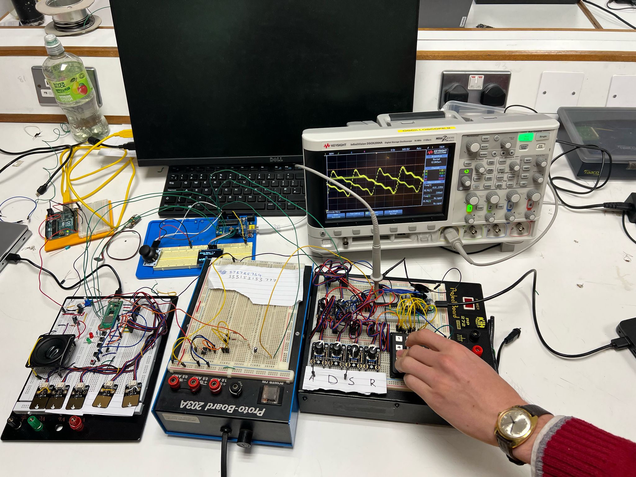
A graphical user interface (GUI) can really improve the user experience, here the GUI serves a few functions. Firstly, it displays the current properties set on the ADSR for tuning. It also functions as an oscilloscope, and can display the wave that is being generated by the keyboard synthesizer. By using the click functionality on the joystick, a user can select from a list of preprogrammed drum loops, which will start playing on the drum via the Pico! Navigation through the GUI works with the flick of the joystick, by flicking left or right, you can cycle through the different screens. By flicking up and down, you can cycle through the different preprogrammed drum loops and songs.
`screen_state`, which ranges from 1-5, and denotes the current screen that will be displayed: a main menu, synthesizer controls, oscilloscope, song selector, and drum selector. The chooseScreen() function continuously reads the joystick's X-axis: pushing right increments `screen_state`, pushing left decrements it, and it wraps around when it goes beyond either end. Each loop iteration then calls `drawScreen()`, which dispatches to the appropriate drawing function for the current mode.
For selecting and playing preprogrammed drum loops `(screen_state == 5)`, the joystick's Y-axis moves a highlighted box through up to four entries ("Money beat", "Hip-Hop", "Funk", "None"), while a click of the joystick button(debounced) commits a choice into `selected_song`. The selected song is conveyed to the Pico, to play the drums.
Throughout the code, "dead-zone" thresholds prevent jitter when the joystick is centered, and brief delay(100) calls debounce menu transitions.
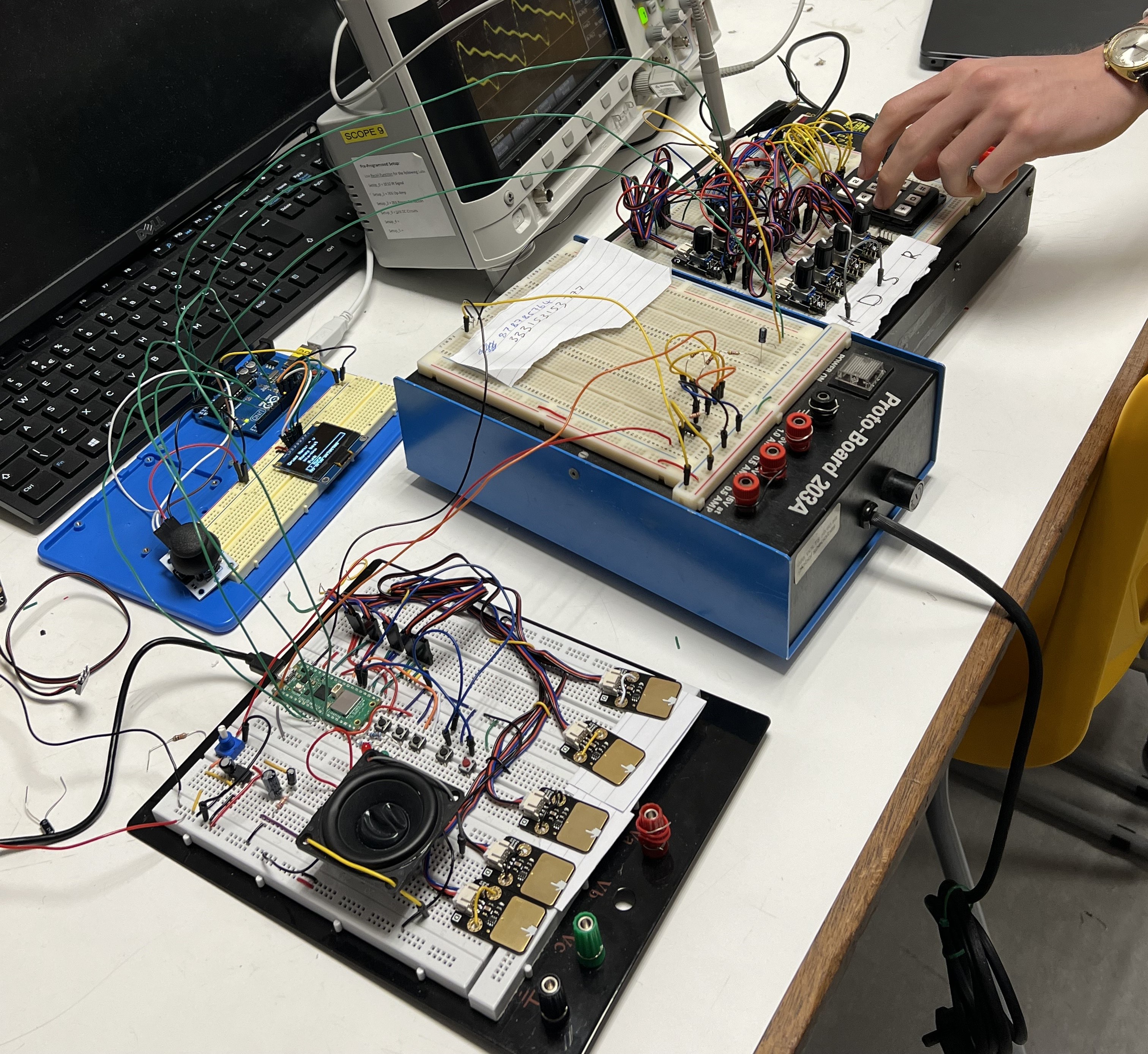
Our DJ table consists of three main hardware components working together to create a complete music production system. This section contains information on how to construct and integrate the final components.
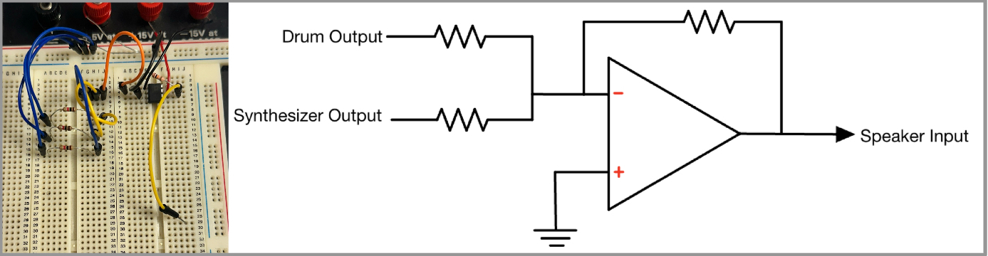
In order to combine all the sounds from the DJ set into a single speaker, a summing amplifier is used. This component takes 2 audio inputs, one from the drum-kit (including audio samples) and the other from synthesizer, and mixes them into a single output signal that is then sent to the power amplifier and then the speaker.
The schematic above illustrates how all components are interconnected to form a cohesive audio system, representing the completed project fully integrated into a functional DJ set. On the right, the synthesizer circuit generates analog audio signals controlled by the ADSR, while the drum module on the left produces digital drum sounds that are converted to analog using a DAC. Both of these outputs are fed into a summing amplifier in the middle, which combines the signals into a single output that drives the speaker on the far left. The GUI, located on the blue tray above, has the ability to play prerecorded songs and beats, as well as display a simplified oscilloscope to visualize changes in the electrical signal over time.
We hope you enjoyed following this blog about our 3C10 Circuits and System project's design process.